

X-ray diffraction(XRD) is an important technique for determining the structures of crystals. The theory behind XRD is a result of pioneering works of the Braggs(father and son).
The main principle behind XRD is the diffraction of X-rays in specific directions by atoms in crystalline structure. Since the interplanar distances in crystals are of the order of Angstroms, therefore X-rays are the suitable choice, as the wavelength of the wave should be of the order of the slit size for the phenomenon of diffraction to take place.
Braggs suggested that the crystal structure can be considered as an array of atoms forming several planes. The X-rays on striking an atom will scatter in some direction. The scattered X-rays can interfere constructively if they are in phase or destructively if they are out of phase. Have a look at the following figure.
The path difference between the two X-rays scattering from the two planes can be easily seen to be 

For the waves to interfere constructively, they should satisfy the following relation
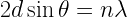
This is the Bragg’s Law.
Here, 
Essentially, we consider the crystal to be a diffraction grating for an X-ray.
XRD pattern: A simple X-ray diffraction experimental setup requires the following: a radiation source, a sample crystal, and a detector. These are arranged as shown in the given figure.

The source gives off X-rays that strike the crystal at some angle 
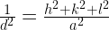
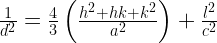
This is done by calculating the interplanar spacing(d) corresponding to a particular peak. And then using a relation between d and the (hkl) indices for different lattice types:
Cubic:
Tetragonal:
Hexagonal:
Rhombohedral:
Orthorhombic:
Monoclinic:
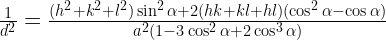
Triclinic:


Generally, a crystal would consist of many planes oriented in different directions. When X-rays strike the crystal at an angle
The following are some of examples of the XRD pattern that one obtains:


Sometimes several diffraction orders are absent due to symmetries in the crystal. Consider the bcc lattice type. The peak corresponding to the (100) is missing in the XRD pattern. This is because at the Bragg angle for these planes, the atoms at the body center, diffract X-rays at 180 degrees out of phase relative to the atoms in the corners. As the number of atoms in the corners is equal to the atoms in the center, the diffracted beams get completely cancelled. Therefore, for a BCC cell, peaks corrsponding to (h+k+l)=odd are absent.
Ph.D. researcher at Friedrich-Schiller University Jena, Germany. I’m a physicist specializing in computational material science. I write efficient codes for simulating light-matter interactions at atomic scales. I like to develop Physics, DFT, and Machine Learning related apps and software from time to time. Can code in most of the popular languages. I like to share my knowledge in Physics and applications using this Blog and a YouTube channel.
PLEASE PROVIDE TIO2 XRD PATTERN AND NAME OF UNIT CELL AND LATTICE COSTT. CALCULATION