

Intro-This is probably my longest post till date, and took me a lot of time to write it. Especially all the research that I had to do to get my concepts straight to be able to answer some of the most common questions rel ated to transmission lines and Lecher lines.
I had this experiment in my M.Sc Physics Waves and Optics lab, so I decided to research and write this post to help students like me struggling with some of the key concepts.
The following is an exhaustive list of some of the frequently asked questions for the experiment: Lecher Line(Wire).
I have tried to provide a lot of useful links in the end of the article for further reading. If you find any typo/suggestion do let me know in the comments below.
Well without further ado, have at it.
- What is a transmission line?
A. A transmission line is a specially designed cable, to transmit alternating current signals of very high frequency(Radio Frequency). - What is the need of a transmission line?
A. Electrical Signals with low frequencies like the ones used in our households(50-100Hz) can be transmitted through the usual copper wires without any significant power losses. However, at high frequencies the losses become significant. They cannot be used to carry currents in the radio frequency range, above about 30 kHz, because the energy tends to radiate off the cable as radio waves, causing power losses. Radio frequency currents also tend to reflect from discontinuities in the cable such as connectors and joints, and travel back down the cable toward the source.These reflections act as bottlenecks, preventing the signal power from reaching the destination.
http://farside.ph.utexas.edu/teaching/em/lectures/node86.html - What is the distinguishing feature between a transmission line and a normal wire?
A. Transmission lines use specialized construction, and impedance matching, to carry electromagnetic signals with minimal reflections and power losses. The distinguishing feature of most transmission lines is that they have uniform cross sectional dimensions along their length, giving them a uniform impedance, called the characteristic impedance, to prevent reflections. - What are some of the common types of transmission lines?
A. Parallel Wire, Microstrip line and Coaxial Cables. - What is a Lecher line?
A. In electronics, a Lecher line or Lecher wires is a pair of parallel wires or rods that were used to measure the wavelength of radio waves, mainly at UHF and microwave frequencies.They form a short length of balanced transmission line (a resonant stub). When attached to a source of radio-frequency power such as a radio transmitter, the radio waves form standing waves along their length. By sliding a conductive bar that bridges the two wires along their length, the length of the waves can be physically measured. - How are standing waves produced in a Lecher line and how can it be used to measure the wavelength?
A. A Lecher line is a pair of parallel uninsulated wires or rods held a precise distance apart. The separation is not critical but should be a small fraction of the wavelength; it ranges from less than a centimeter to over 10 cm. The length of the wires depends on the wavelength involved; lines used for measurement are generally several wavelengths long. The uniform spacing of the wires makes them a transmission line, conducting radio waves at a constant speed very close to the speed of light. One end of the rods is connected to the source of RF power, such as the output of a radio transmitter. At the other end the rods are connected together with a conductive bar between them. This short circuiting termination reflects the waves. The waves reflected from the short-circuited end interfere with the outgoing waves, creating a sinusoidal standing wave of voltage and current on the line. The voltage goes to zero at nodes located at multiples of half a wavelength from the end, with maxima called antinodes located midway between the nodes. Therefore the wavelength λ can be determined by finding the location of two successive nodes (or antinodes) and measuring the distance between them, and multiplying by two. The frequency f of the waves can be calculated from the wavelength and the speed of the waves, which is the speed of light c:The nodes are much sharper than the antinodes, because the change of voltage with distance along the line is maximum at the nodes, so they are used.
- How can you find out the locations of two successive nodes and hence the wavelength?
A. The method used to find the nodes is to slide the terminating shorting bar up and down the line, and measure the current flowing into the line with an RF ammeter in the feeder line. The current on the Lecher line, like the voltage, forms a standing wave with nodes (points of minimum current) every half wavelength. So the line presents an impedance to the applied power which varies with its length; when a current node is located at the entrance to the line, the current drawn from the source, measured by the ammeter, will be minimum. The shorting bar is slid down the line and the position of two successive current minima is noted, the distance between them is half a wavelength.With care, Lecher lines can measure frequency to an accuracy of 0.1%. - What are some applications of the Lecher line?
A.Lecher line can act as a tank circuit in an RF amplifier . Short lengths of Lecher line are often used as high Q resonant circuits , termed resonant stubs . For example, a quarter wavelength (λ/4) shorted Lecher line acts like a parallel resonant circuit, appearing as a high impedance at its resonant frequency and low impedance at other frequencies. They are used because at UHF frequencies the value of inductors and capacitors needed for ‘lumped component ‘ tuned circuits becomes extremely low, making them difficult to fabricate and sensitive to parasitic capacitance and inductance. One difference between them is that transmission line stubs like Lecher lines also resonate at odd-number multiples of their fundamental resonant frequency, while lumped LC circuits just have one resonant frequency. - What information can you get from the ratio of the maximum and minimum current?
A. The ratio of the min. and max. current is equal to the ratio of the characteristic impedance to the load impedance. - What is the characteristic impedance of a Lecher Line?
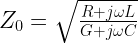
A. The characteristic impedance or surge impedance (usually written Z0) of a uniform transmission line is the ratio of the amplitudes of voltage and current of a single wave propagating along the line; that is, a wave travelling in one direction in the absence of reflections in the other direction. Characteristic impedance is determined by the geometry and materials of the transmission line and, for a uniform line, is not dependent on its length. The SI unit of characteristic impedance is the ohm.
Applying the transmission line model based on the telegrapher’s equations, the general expression for the characteristic impedance of a transmission line is:where
is the resistance per unit length, considering the two conductors to be in series,
is the inductance per unit length,
is the conductance of the dielectric per unit length,
is the capacitance per unit length,
is the imaginary unit, and
is the angular frequency
For a lossless line, R and G are both zero, so the equation for characteristic impedance derived above reduces to:

- What is the input impedance of a transimission line?
A. The characteristic impedance Z0 of a transmission line is the ratio of the amplitude of a single voltage wave to its current wave. Since most transmission lines also have a reflected wave, the characteristic impedance is generally not the impedance that is measured on the line.The impedance measured at a given distance, l, from the load impedance ZL may be expressed as,where γ is the propagation constant and
is the voltage reflection coefficient at the load end of the transmission line. Alternatively, the above formula can be rearranged to express the input impedance in terms of the load impedance rather than the load voltage reflection coefficient:
- Does the position of the standing wave depend upon the separation between the wires?
A. The separation between the Lecher bars does not affect the position of the standing waves on the line, but it does determine the characteristic impedance, which can be important for matching the line to the source of the radio frequency energy for efficient power transfer. - Does the position of the standing wave depend upon load resistance?
A. The position of the standing wave changes for different load impedance.
- What is the expression for reflection coefficient for Lecher Line?
A. Reflection coefficient is the ratio of the voltage of the reflected wave to that of the incident(forward) wave.
- What is the condition for maximum power transfer? What is the value of reflection coefficient for this?
A. For maximum power transfer, there should be no reflected wave. Therefore, the reflection coefficient should be 0.
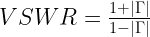
- What is VSWR(Voltage Standing Wave Ratio)?
A. VSWR is the ratio, also referred to as Standing Wave Ratio (SWR) is the ratio of the maximum value of the voltage to the minimum value of voltage measured along the transmission line. It’s significance lies in the fact that it is also the ratio of the load impedance to the characteristic impedance, and hence useful for impedance matching. For example, the VSWR value 1.2:1 denotes an AC voltage due to standing waves along the transmission line reaching a peak value 1.2 times that of the minimum AC voltage along that line. The SWR can as well be defined as the ratio of the maximum amplitude to minimum amplitude of the transmission line’s currents, electric field strength, or the magnetic field strength. Neglecting transmission line loss, these ratios are identical. - What is Power Standing Wave ratio (PSWR)?
A. The power standing wave ratio (PSWR) is defined as the square of the VSWR, however this terminology has no physical relation to actual powers involved in transmission. - What is the relation between reflection coefficient and VSWR?
A. VSWR is related to the reflection coefficientas:
Proof:
We know that,
When the incident and the reflected waves interfere, constructively along the line such that they are exactly in phase, then we get maximum voltage,
and when the waves interfere destructively and are totally out of phase(180 degrees) then the voltage is minimum,
Therefore,
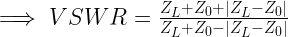
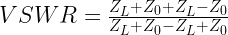
- What is the relation between VSWR, characteristic impedance and the load impedance?
A. VSWR can also be expressed in terms of ZL and ZO. We have already proven that
Also,(Proved later on)
Plugging the second equation(expression for),
For
Therefore,
For
Therefore,
- What is the value of the reflection coefficient when the circuit is open, short, and perfectly matched?
A.: complete negative reflection, when the line is short-circuited,
: no reflection, when the line is perfectly matched,
: complete positive reflection, when the line is open-circuited.
The SWR directly corresponds to the magnitude of
- What is the value of VSWR when the circuit is open, short, and perfectly matched?
A. VSWR is infinte for an open/short line. It is 1 for a perfectly matched line. - When is the value of VSWR highest?
A. Highest VSWR values occur when there is no load connected to the end of the line. This condition, known as an unterminated transmission line, is manifested when the end of the line is either short-circuited or left open. In theory, the SWR is infinite in either of these cases; in practice, it is limited by line losses, but can exceed 100. This can give rise to extreme voltages and currents at certain points on the line. - Give an analysis of the standing waves produced for Voltage and Current for the following cases: (i) Open End, (ii) Closed End, (iii) Matched Impedance.
A. If the wires of the Lecher line are short-circuited at the end, then the voltage U is zero. A reflected wave arises with a phase shift of 180 degrees with respect to the incoming wave. For example, a voltage wave
coming in from the left together with a jumper at
gives rise to the reflected wave
. Both waves interfere to form the standing wave
. The voltage between the wires is associated with a charge distribution along the wires. The displacement of these charges leads to a current I in the wires which propagates as a wave. There must be a permanent current at the jumper. The incoming current wave I1 = I0 ⋅ sin(vt − kx) is therefore reflected without a change in phase; that is, the reflected current wave has the form I2 = I0 ⋅ sin(vt + kx). I1 and I2 interfere to form the standing wave I = I1 + I2 = 2 ⋅ I0 ⋅ cos kx ⋅ sin vt (III). Eqs. (II) and (III) show that the nodes of the voltage wave just correspond to the antinodes of the current wave and the antinodes of the voltage wave to the nodes of the current wave. The positions of the voltage nodes are
- What is the difference in the standing waves produced in an open and closed end lecher line?
A. The figure shows the Voltage standing waves produced for open and closed Lecher line respectively. As is clearly apparent, the waves produced differ in phases. The wave reflects as though it is reflecting from a hard boundary in case of an open Lecher line, while it reflects as though it is reflecting from a soft boundary for a closed Lecher line. More info: http://www.acs.psu.edu/drussell/Demos/reflect/reflect.html
 - Give an analysis of the Standing Waves for arbitrary impedance?
A. For the general case of a line terminated in some arbitrary impedance it is usual to describe the signal as a wave travelling down the line and analyse it in the frequency domain. The impedance is consequently represented as a frequency dependent complex function.
Equivalent circuit of a transmission line incident wave arriving at an arbitrary load impedance. Source Self created using Inkscape Date 25th August 2009 Author SpinningSpark Fig. Equivalent circuit of an incident wave on a transmission line arriving at an arbitrary load impedance.
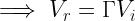
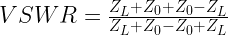
For a line terminated in its own characteristic impedance there is no reflection. By definition, terminating in the characteristic impedance has the same effect as an infinitely long line. Any other impedance will result in a reflection. The magnitude of the reflection will be smaller than the magnitude of the incident wave if the terminating impedance is wholly or partly resistive since some of the energy of the incident wave will be absorbed in the resistance. The voltage,
, across the terminating impedance,
, may be calculated by replacing the output of the line with an equivalent generator (figure) and is given by
The reflection,
must be the exact amount required to make
,
The reflection coefficient,
and substituting in the expression for
In general
when
The physical interpretation of this is that the reflection cannot be greater than the incident wave when only passive elements are involved (but see negative resistance amplifier for an example where this condition does not hold). For the special cases described above,
Termination Open circuit Short circuit
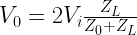
When both
and


![VSWR=\left[\frac{1+\left|\frac{Z_L-Z_0}{Z_L+Z_0}\right|}{1-\left|\frac{Z_L-Z_0}{Z_L+Z_0}\right|}\right]](https://s0.wp.com/latex.php?latex=VSWR%3D%5Cleft%5B%5Cfrac%7B1%2B%5Cleft%7C%5Cfrac%7BZ_L-Z_0%7D%7BZ_L%2BZ_0%7D%5Cright%7C%7D%7B1-%5Cleft%7C%5Cfrac%7BZ_L-Z_0%7D%7BZ_L%2BZ_0%7D%5Cright%7C%7D%5Cright%5D+&bg=ffffff&fg=000&s=2&c=20201002)


Well, that’s it! Hope you find it useful.
References:
- https://www.allaboutcircuits.com/textbook/alternating-current/chpt-14/50-ohm-cable/
- https://www.allaboutcircuits.com/textbook/alternating-current/chpt-14/characteristic-impedance/
- http://alignment.hep.brandeis.edu/Lab/XLine/XLine.html
- http://www.antenna-theory.com/tutorial/txline/transmissionline.php#txline
- https://www.maximintegrated.com/en/app-notes/index.mvp/id/5432
- http://www.iitk.ac.in/mimt_lab/vlab/txl_fd/doc/transmission_line_frequency_domain.pdf
- https://en.wikipedia.org/wiki/Standing_wave_ratio
- https://en.wikipedia.org/wiki/Transmission_line
- https://en.wikipedia.org/wiki/Lecher_lines
- http://farside.ph.utexas.edu/teaching/em/lectures/node86.html
- https://en.wikipedia.org/wiki/Standing_wave
- http://whatis.techtarget.com/definition/standing-wave-ratio-SWR-VWSR-IWSR
- http://www.phy.fju.edu.tw/files/archive/217_72222f07.pdf
- http://pec.sjtu.edu.cn/ols/P3/P3731_E.PDF
- http://www.acs.psu.edu/drussell/Demos/reflect/reflect.html
- http://www.acs.psu.edu/drussell/Demos/SWR/SWR.html
- https://en.wikipedia.org/wiki/Reflections_of_signals_on_conducting_lines
- http://www.hit.ac.il/.upload/engineering/Experiment_3_-_Transmission_lines,_Part_1.pdf
Ph.D. researcher at Friedrich-Schiller University Jena, Germany. I’m a physicist specializing in computational material science. I write efficient codes for simulating light-matter interactions at atomic scales. I like to develop Physics, DFT, and Machine Learning related apps and software from time to time. Can code in most of the popular languages. I like to share my knowledge in Physics and applications using this Blog and a YouTube channel.
Hello,
In the above post you state; “With care, Lecher lines can measure frequency to an accuracy of 0.1%.” Is there a citation or study that supports this claim? I ask as it is important to current research of mine. If there is anyplace I can find supporting evidence, it would be greatly appreciated.
I’m sorry for the late reply. This was mentioned on the Wikipedia (https://en.wikipedia.org/wiki/Lecher_line#:~:text=With%20care%2C%20Lecher%20lines%20can,to%20an%20accuracy%20of%200.1%25.) with the following reference
https://en.wikipedia.org/wiki/Lecher_line#cite_note-Endall-1