

The following are some of the frequently asked question (faq) about the Scintillation Counter/Detector:
Q.What is scintillation efficiency?
A. Scintillation Efficiency can be defined as the ratio of the energy of the scintillation light to the energy deposited.
Q. Is the scintillation efficiency of the crystal a constant?
A. For all scintillators, the scintillation efficiency or amount of light generated per unit energy loss (dLldE) depends both on the particle type and its kinetic energy. For an ideal spectrometer, dLldE would be a constant independent of particle energy. The total light yield would then be directly proportional to the incident particle energy, and the response of the scintillator would be perfectly linear. The scintillation efficiency changes with size and shape of the crystal as well as the size and physical nature of the source. It also depends upon the distance of the source from the detector. The following graphs show how the scintillation efficiency of NaI(Tl) varies with energies.  Q.For NaI(Tl) detector what should be the work function of the photocathode being used in the PMT?
A. The energy of the scintillation photons emitted by NaI(Tl) is ≈3eV. Therefore the photocathode must have a work function less than 3eV so that photoelectrons can be emitted with enough K.E. to reach the dynode. Typically metals have work function 3 ~ 4 eV which is not good. Therefore specially developed alloys (bialkali, multialkali) with Work function = 1.5 ~ 2 eV are used.
Q.What are some of the factors that must be kept in mind while choosing a particular photocathode?
A. The photocathode should meet the following criteria:
i) It’s workfunction should be less than the energy of the scintillation photons.
ii) In addition, the thickness of the material that can generate photoelectrons into the vacuum is limited, because there is a rate of energy loss as the electron migrates to the surface. For metals this energy loss rate is relatively high and an electron will have its energy drop below the potential barrier after traveling only a few nanometers. In semiconductors the electron can travel 20 – 30 nanometers, before its energy drops below the barrier. In either case only a thin layer of material contributes photoelectrons into the vacuum. The cathodes are sometimes designed so that the light is incident on one side, while the electrons are ejected on the other. The photocathode is therefore extremely thin, because of the problems of electron interaction in the material, and is therefore semi-transparent to visible light. This means that a large proportion (more than half) of the light passes straight through without interacting with the photocathode.
iii) It should be sensitive enough to produce enough photoelectrons. The quantum efficiency of the photocathode is defined as the probability for the conversion of light to an electrical signal and is given by
Quantum efficiency = number of photoelectrons emitted/ number of incident photons
Usually materials used as Photocathode have an average Q.E. of 15-20%.
Also, Q.E. is function of wavelength of the incident photon. The following figure shows the variation of Q.E. for various materials versus wavelength of the incident photon.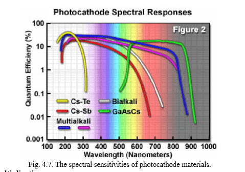
So while the Bialkali photocathode would be good for scintillation photons lying in the UV-Blue range, one would want to employ a GaAsCs photocathode for Red Scintillation photons.
Q.How is a single gamma ray photon of high energy (say, 662keV) converted into several scintillation photons of ≈3eV energy in an NaI(Tl) crystal?
A.The Scintillation Process in NaI(Tl) Thallium-activated sodium iodide is crystalline in physical form, with a small amount of thallium replacing sodium (about 1 in 1000 atoms) to provide the impurity. It is the delocalized molecular bonding of the crystal that gives it the ability to scintillate. Briefly, the electron orbitals of the sodium and iodine atoms combine to form a valence band and a conduction band of molecular orbitals. The valence band (analogous to the bonding orbital of a covalent bond) is at a lower energy than the conduction band (analogous to the antibonding orbital). The thallium impurities create electron orbitals between the conduction band and the valence band called activation centres. In the ground state, the valence band and the ground-state level of each activation centre are filled with electrons. The conduction band and the excited energy levels of the activation centres are empty. Thus there is no electron movement in the absence of radiation.
 When a gamma ray enters the crystal and undergoes an interaction, it produces one or more secondary electrons with high kinetic energy. These electrons cause ionizations and excitations as they move, creating many low-energy electrons. Most of these low-energy electrons lose their energy as heat, but some have the right amount of energy to jump up to the conduction band (Fig. Step a). A hole is left in the valence band for each electron excited to the conduction band. The electrons that get into the conduction band are free to move around, but are not allowed to drop directly back into the valence band (this is “forbidden,” meaning highly unlikely according to quantum mechanics). However, they will still seek to find the lowest energy levels available to them, which are the excited state levels of the activation centres (Fig. Step b). Likewise, the holes will allow electrons in the valence band to move, and eventually they will be filled by electrons from activation centres, leaving vacancies in the activation centre ground-state orbitals. Quantum mechanics does allow the transition of an electron from the excited state to the ground state in an activation centre. The electron drops down and fills the hole, with the release of the excess energy in the form of a scintillation photon of energy 3eV which is the band gap. (Fig. Step c).
Q.Explain the Scintillation process for NaI(Tl).
A. Same as above.
Q.Why are the heights of the pulses from the amplifier not all the same?
A. The height of the pulses depends upon the energy deposited to the scintillator by the incident gamma ray. And as the energy deposited depends on various kinds of interactions that the radiation can have with the detector, therefore the height of all the pulses is not the same.
Q.Does the amplitude of the pulses depend upon the PMT voltage? If yes then why?
A. Yes the amplitude of the pulses depends upon the PMT voltage. Higher PMT voltage means a higher dynode potential, which consequently means that the primary and the secondary electrons are accelerated towards the dynodes with higher energies and are thus capable of producing more secondary electrons. Hence the amplification factor of a PMT is increased.
Q.How would you adjust the amplifier such that the voltage corresponding to the maximum energy deposition is ~6V? (like you did in the case for Cs-137)
A. We would observe the output of the Amplifier on an Oscilloscope and find out the maximum amplitude of the pulses. If it is not ~6V then we increase or decrease the amplifier gain accordingly using the fine or coarse gain knobs.
Q.How many types of PHA (Pulse Height Analyser) are there and how do they work?
A. PHA’s are of two types:
SCA (Single-Channel Analyser): An SCA consists of a lower level discriminator(LLD), an upper level discriminator(ULD), and an anticoincidence logic circuit. The values of LLD and ULD are set by the operator and related to the energy of the photons being measured. Each pulse in turn is compared to the LLD and ULD, and the pulses with amplitude greater than LLD but less than ULD , as detected by the anticoincidence logic circuit produce PHA pulses. All output pulses from the PHA are the same size and are sent to the scaler.
In some detectors the there is a knob on the electronics module to make it work in the window mode. In the window mode the ULD knob acts as a window. In window mode the SCA returns “1” for pulses lying between LLD voltage and LLD + window voltage.
MCA (Multi-Channel Analyser): An MCA shows all radiation events on an energy graph or pulse-height spectrum. Most MCAs work by digitising the PMT output, and assigning the event to one of a series of predefined bins or channels based on the signal’s size. We can think of an MCA as consisting of a series of SCA’s each representing a small portion of the energy spectrum. Each gamma ray is recorded as a “1” in one SCA and a “0” in all other SCA’s.
Q.Which is better, an MCA (Multi-Channel Analyser) or SCA (Single-Channel Analyser), and why?
A. An MCA is better as pulses of all the energies are registered simultaneously, i.e., all the radiation events are recorded. In an SCA, however, a lot of potentially useful information is lost while we are looking for pulses that lie within a specific voltage range as specified by the LLD and ULD.
Q.What do the voltages of pulses obtained from the amplifier signify?
A. The voltage of a pulse is directly proportional to the energy deposited to the scintillation material.
Q.What do the counts of your measurements signify?
A. The counts that we get in a particular time interval is the no. of pulses lying in a voltage range as set by the PHA (SCA). When we look at the gamma ray spectrum of a source we can tell that which process (gamma ray interaction) was more probable based on the counts.
Q.Does the output of the PHA pulse depend upon the amplitude of the input pulse from Amplifier?
A. No. All output pulses from the PHA are of same size. It either accepts or rejects a pulse based on its voltage and sends out a string of logic (yes/no or 1/0) pulses that can be counted.
Q.If the voltage of the output pulse from the Amplifier is directly proportional to the energy deposited at the scintillator then why don’t you get the same voltage every time the same amount of energy is deposited?
A. A lot of energy (photon) to mass (electron) conversions take place in the whole process of obtaining a voltage pulse corresponding to an event (gamma ray interaction)(In total 3 conversions take place). There is some inefficiency associated with each conversion and therefore a loss of energy. Therefore the no. of secondary electrons recorded at the anode for a particular energy deposition has a statistical variation. Therefore the measured output (pulse height) is not always proportional to the energy deposited but has some random fluctuations. As a result we do not get a distribution of pulse heights with a Gaussian shape.
Q.Explain the finite width of the photoelectric peak distribution.
A. Same as above.
Q.What could you say about the probabilities of an interaction process by looking at the gamma ray spectra for a particular source?
A. The counts corresponding to a particular event in the spectrum of a source indicate the probability of that event. The probability of interacting with matter in each of the three processes (Photoelectric absorption, Compton scattering, Pair production) can be expressed as an absorption coefficient, also called a linear attenuation coefficient. For all three processes, the total attenuation coefficient µ is the sum of the three partial attenuation coefficients:
µtotal=µphotoelectric+µcompton+µpair production
 Q.Explain why you get a relatively higher photopeak for Cs-137 and Co-57 as compared to Na-22 or Co-60.
A. The probability of Photoelectric absorption is more for lower energies as compared to higher energies. (Refer Figure) Therefore, less events corresponding to Photoelectric absorption are registered for high energy gamma rays resulting in a lower number of counts and hence a shorter peak.
Q. Show the decay process for Cs-137, Na-22, Co-57 and Co-60.
A. Cs-137 is a standard calibration source with a single gamma line. As shown in figure below, the nuclear decays starts with β emission, 5.4% of the time directly to the ground state, and the rest of the time to a short-lived intermediate state that decays by emission of a 0.662 MeV γ . The β ’s are stopped in the casing of the scintillator, but the γ ’s are penetrating.
 Q. Explain the source of a peak around 32 keV in the Cs-137 spectra.
A. The source of the peak is the characteristic x-rays from barium. Caesium 137 decays by the emission of a beta particle that occurs by the transformation of a neutron into an electron and proton. With the emission of the beta particle (the electron) the caesium nucleus is left with an additional proton making it a barium nucleus in a metastable excited state, barium 137m. The excited barium 137m (137mBa) nucleus then decays down to its ground state by the emission of a 0.662 MeV gamma ray about 85% of the time. This is the gamma ray that is responsible for the photopeak. Not all of the barium nuclei de-excite by this mechanism though. As a competing process some nuclei transfer their excitation energy to a K-shell electron, kicking the electron out of the atom with a kinetic energy of 0.662 MeV less the binding energy needed to free the electron from being bound to the nucleus. This leaves a vacancy in the K shell that is filled with either an L-shell or M-shell electron resulting in the emission of either a Kα1 or Kα2 X-ray with an energy of 32.2 keV or 31.8 keV, respectively.
Cs-137 is a great all-around spectroscopy calibration source. We get the 662-kev gammas for gamma spectroscopy, you get the barium x-rays for x-ray spectroscopy.
Q. Explain the source of the peak around 511keV in the Na-22 spectra.
A. Sodium–22 is similar to Caesium 137; there is a beta transition followed by a single electromagnetic transition which emits a 1.277 MeV gamma ray. However, unlike caesium, the beta ray is this case is a positron, the antiparticle of the electron. This positron will typically annihilate with an electron in the source or the cladding, through the “two-photon annihilation” process
e+ + e– → γ + γ yielding two back-to-back gamma rays with with Eγ = mec2 = 511keV. And since the two photons go in opposite directions to conserve momentum, therefore only one of them makes it to the detector and therefore we see a peak at 511 keV.
Q.Explain how the Na-22 spectrum can be used to measure the rest mass of electron.
A. The 511keV peak in the Na-22 spectrum results from the annihilation of the positron and electron. Since the process results in two photons of energy equal to the rest mass energy of electron,
e+ + e– → γ + γ with Eγ = mec2 = 511keV therefore, we can verify/measure the rest mass of electron.
Also we are seeing the laboratory manifestation of the famous E=mc2 formula.
Q.What is known as the valley in the gamma ray spectra?
A. The valley is the region between E(energy of the gamma ray) and Ec where Ec is the maximum energy for Compton scattering. Pulses lying within this region are infrequently produced as there is no physical interaction process that would lead to energy deposition within this range. Thus, the region between the Compton edge and the photopeak should be void of pulses. However, due to the moderate resolution of the detector, the void is filled on either side resulting in a V-shaped depression known as the “valley”.
Q.Is the resolution of the detector dependent on the energy of the gamma ray.
A. Yes, the resolution decreases for gamma rays with high energies.

References:
1. For the properties of photocathode: https://www.science.mcmaster.ca/medphys/images/files/courses/4R06/note4.pdf
- For the linear attenuation coefficient (image):
http://www.lanl.gov/orgs/n/n1/panda/00326397.pdf - Scintillation Detector Manual:
http://samples.jbpub.com/9780763766382/66382_CH02_Prekeges.pdf - Explanation of spectrum of Na-22, Co-60, Cs-137:
http://instructor.physics.lsa.umich.edu/adv-labs/gamma_spectroscopy/gamma_ray_spectroscopy.pdf - Scintillation Efficiency of Crystal:
Radiation and Detection Measurement- G. F. Knoll Pg 333
http://nicadd.niu.edu/research/extruder/extruder_files/doc/Scintillator%20Radiation%20Damage/radiation6.pdf - Explanation of the characteristic X-rays from Ba-137:
http://www.compadre.org/advlabs/bfyii/files/ComptonScatteringExperimentRev3.0020150106.pdf
Ph.D. researcher at Friedrich-Schiller University Jena, Germany. I’m a physicist specializing in computational material science. I write efficient codes for simulating light-matter interactions at atomic scales. I like to develop Physics, DFT, and Machine Learning related apps and software from time to time. Can code in most of the popular languages. I like to share my knowledge in Physics and applications using this Blog and a YouTube channel.
Please tell me how PMT forms pulses and how we get different voltages for Compton Scattering and Photoelectric?
Thanks!